Tempco Blog articles

ATEX zone TCU temperature control units, maximum efficiency with control panel in safe area

The highest level of safety for temperature control units (TCU) in ATEX zones is achieved by installing the control panel outside the explosive hazard area, adopting a dual-configuration approach.

In a previous post, we explored the challenges and solutions regarding temperature control in ATEX environments, focusing on the design of safe and efficient thermoregulation units. As previously mentioned, one of the most effective strategies for optimizing temperature control in these applications is to separate the control panel from the hazardous area by installing it in a safe zone. This configuration offers numerous advantages in terms of safety, reliability, and operational management.

Dual-configuration approach: ATEX TCU + Remote control
To ensure optimal temperature control in explosive hazard zones, temperature control units (TCUs) are frequently designed as two separate units:

  • The TCU itself, installed within the ATEX area
  • A remote control panel, positioned in a safe zone

This solution eliminates the need for complex electronic devices within the ATEX area, thereby reducing the risk of failure and simplifying maintenance.

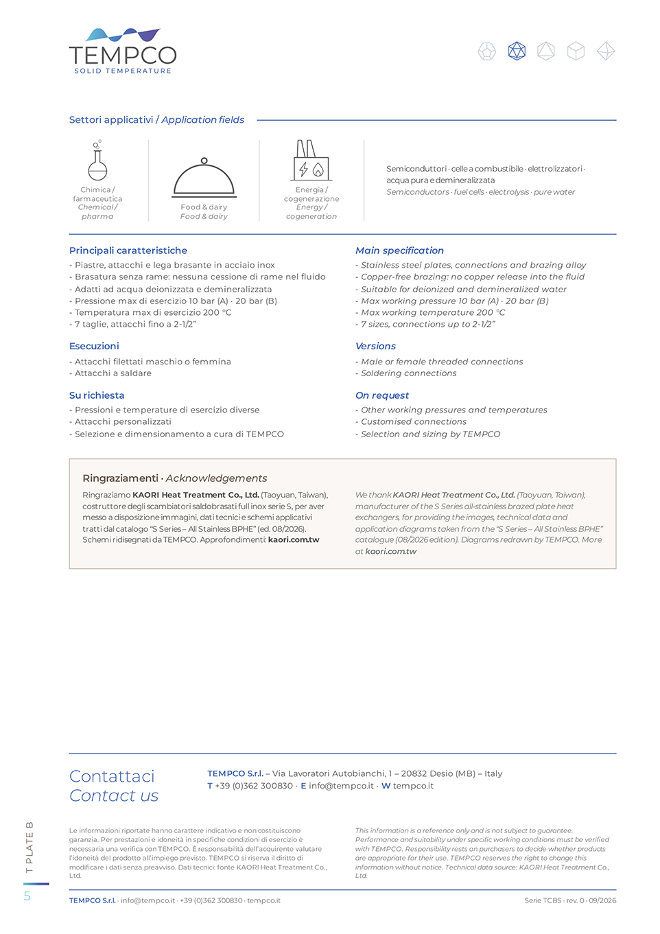
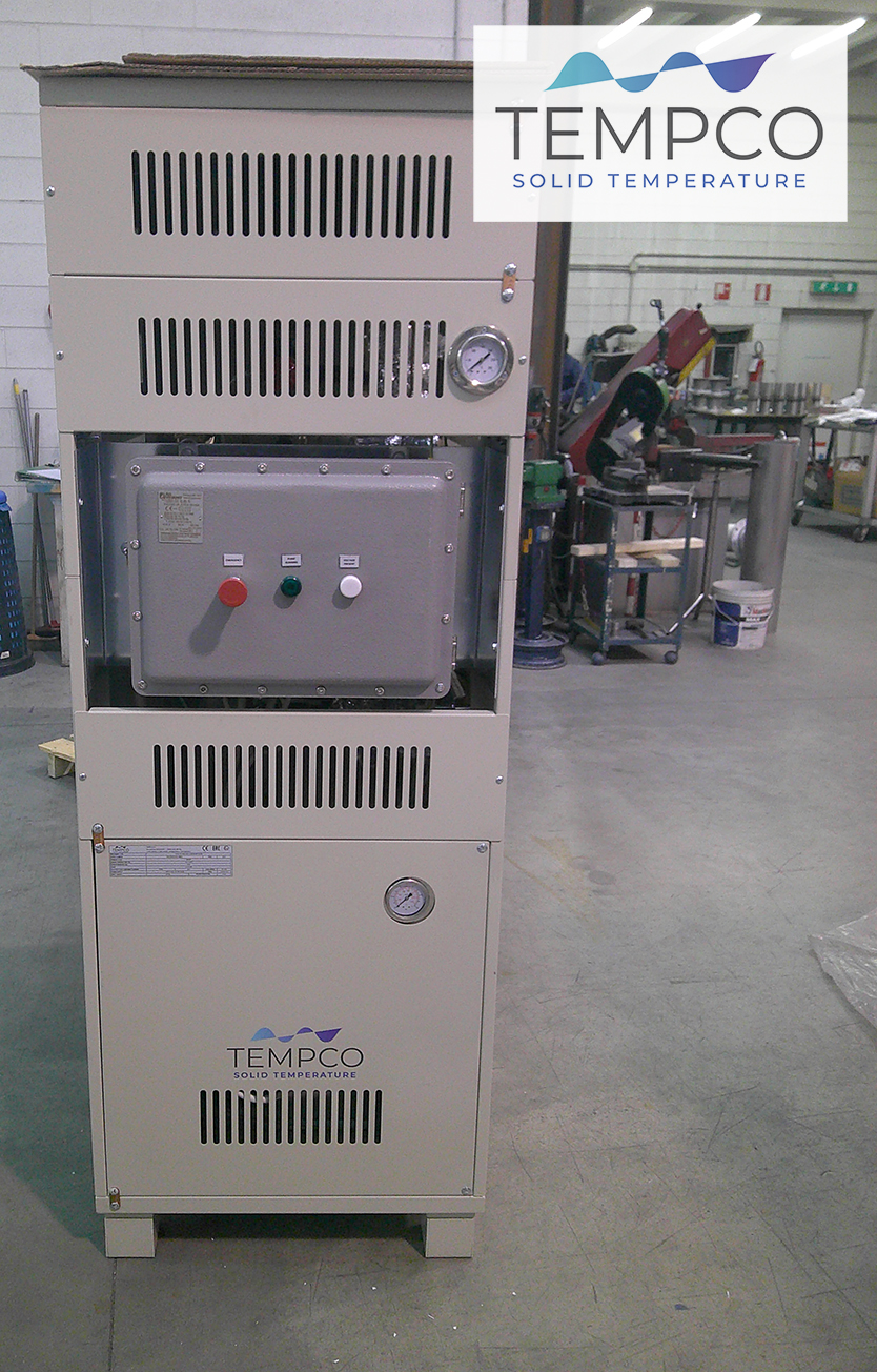
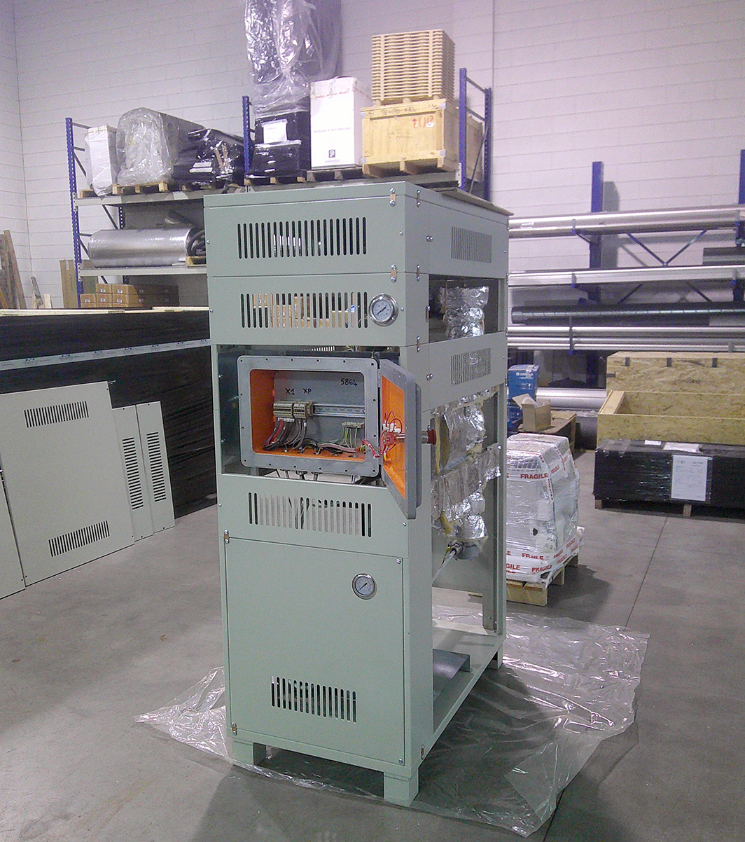
Image showing a temperature control unit (TCU); for ATEX zone installations, a dual configuration with a separate control panel in a safe zone allows to use advanced electronics to ensure maximum efficiency and reliability.

The dual-configuration solution therefore comprises several key components:

  1. Temperature Control Unit (TCU) in the ATEX zone
    The unit installed in the ATEX zone houses all components involved in the temperature control process, designed with appropriate protection measures:
    Heat exchangers and thermal circuits constructed using materials and configurations compliant with ATEX standards.
    • Explosion-proof electric heating elements.
    • Intrinsically safe certified temperature sensors (PT100, thermocouples).
    • Actuators and valves with Ex d or Ex i protection for thermal flow control.
    • Special shielded and insulated wiring to prevent overheating and leakage.
  2. Control panel in the safe zone
    The heart of the temperature control system is located in a non-hazardous area, allowing for the implementation of advanced electronics without ATEX constraints:• Industrial PLC for temperature management featuring advanced PID control.
    • Touchscreen HMI for monitoring and manually adjusting TCU parameters.
    • Data logging and reporting capabilities for thermal performance analysis.
    • Remote management via connection to SCADA or cloud systems.


Image showing a temperature control unit (TCU); for ATEX zone installations, a dual configuration with a separate control panel in a safe zone allows for the use of advanced electronics to ensure maximum efficiency and reliability.

Brazed plate heat exchangers: when immediate availability makes the difference

Market lead times for the delivery of brazed plate heat exchangers have recently increased significantly, often stretching into weeks or months. At Tempco, we have taken a different approach: we stock over 1,000 brazed plate heat exchangers in Italy, ready for immediate shipment, to meet the majority of common requests without delay.

Brazed plate heat exchangers consist of stainless steel plates joined via copper or nickel brazing. They offer maximum heat transfer efficiency within a compact footprint, making them ideal for heat transfer where space is limited. Furthermore, the brazing process creates a plate pack with superior mechanical strength, enabling operation at higher pressures and across wider temperature ranges.

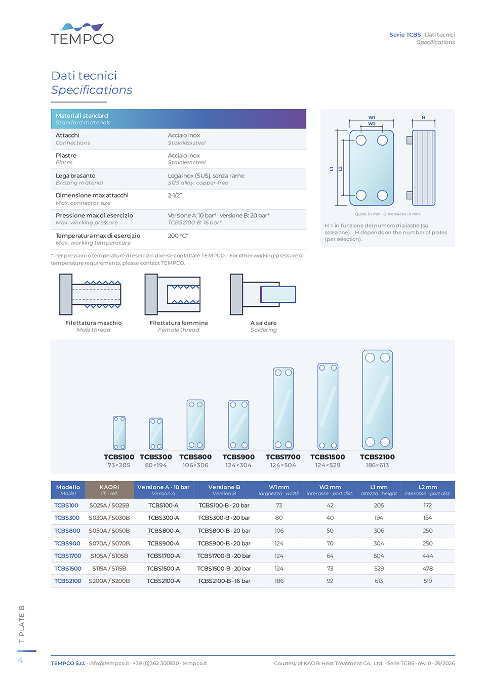
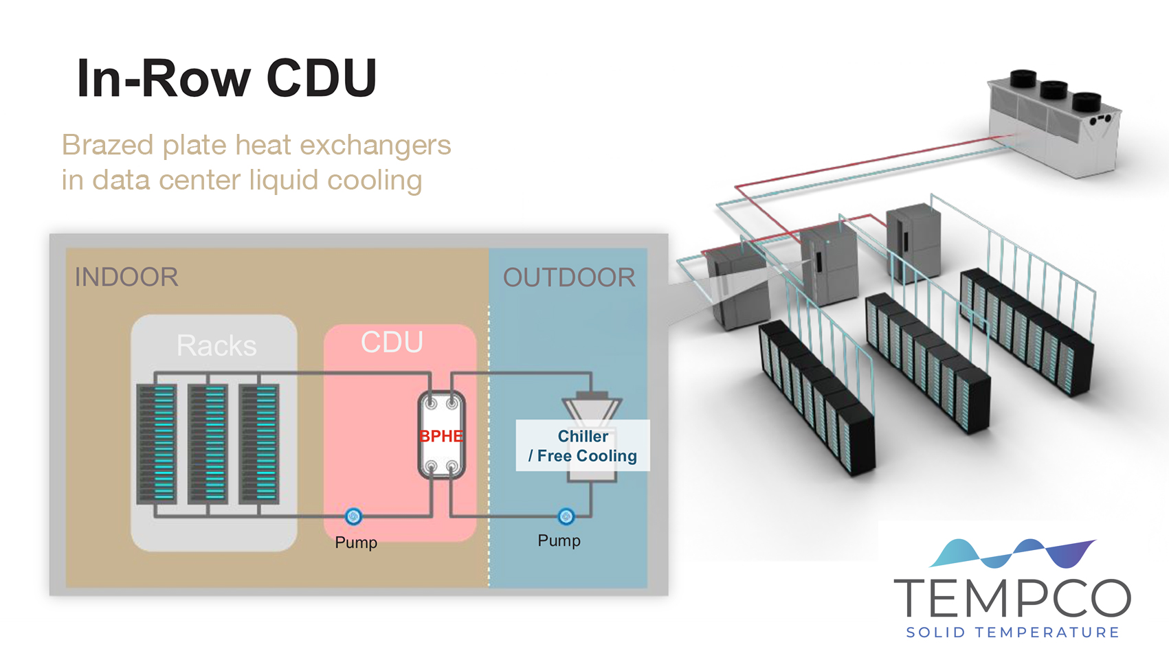
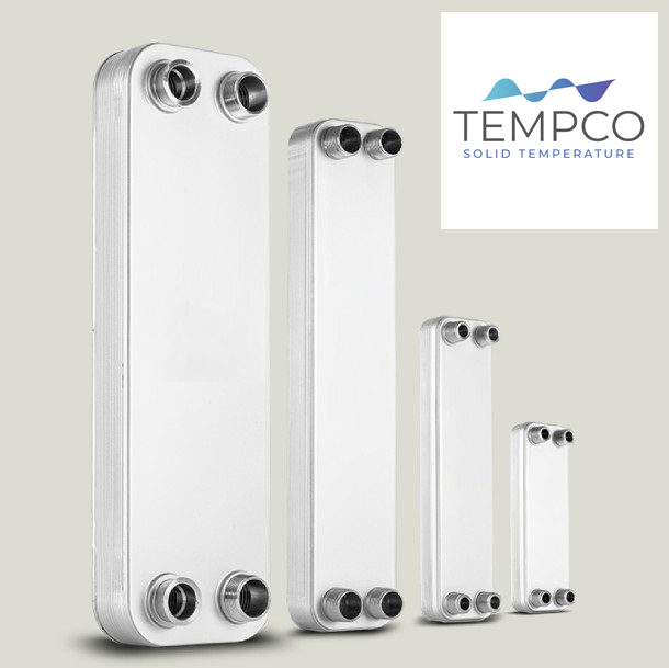
Image showing a range of brazed plate heat exchangers—a type of unit Tempco offers for immediate delivery, thanks to an Italian warehouse stock of over 1,000 units.

Immediate availability applies to models with standard connections and ports up to 2″. By focusing on the most common sizes and configurations, Tempco can respond promptly to urgent needs, replacement requests, and equipment downtime. In such situations, the quick delivery of a heat exchanger makes the difference between getting a system back up and running immediately vs suffering costly shutdowns.

Let’s discuss your needs
If you have a system to complete, a machine that is down, or wish to get ahead of market price increases, please contact us with the required size and connection specifications; we will check immediate availability and shipping times together.

Cutting oil cooling with immersion heat exchangers

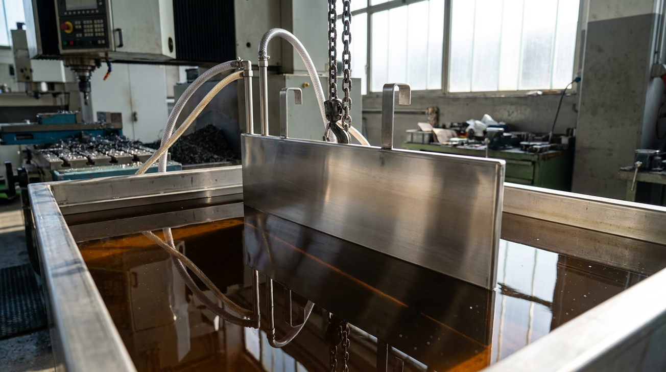
In precision machining workshops, cutting oil in the collection tank heats up during the work shift, negatively affecting machining operations and tooling, specifically impacting machining precision and tolerances. A Tempco gear-manufacturing customer reported an issue with a tank that would exceed 45°C within just a few hours due to the lack of a dedicated cooling circuit.

The simplest and least intrusive solution for this specific application was a stainless steel TCOIL heat exchanger immersed directly into the cutting oil tank. This solution required no machine modifications, allows for direct heat transfer with the oil, and can be supplied with water from a cooling tower, chiller, or well.

Image illustrating a TCOIL immersion heat exchanger for cooling cutting oil in a machining workshop; it offers minimal installation requirements and direct heat transfer with the oil through direct immersion in the collection tank.

The solution proposed by Tempco therefore offers several advantages for this application:

  • Minimal installation: the TCOIL immersion heat exchanger is placed directly into the cutting oil tank, requiring no machine modifications or additional process piping.
  • Direct fluid contact: heat exchange occurs directly within the oil, eliminating the need for pumps or secondary circuits on the process side.
  • Customized materials: AISI 304/316 stainless steel to withstand oil, emulsions, and harsh environments.
  • Flexible supply: the coil can be fed with cooling tower water, chiller water, or well water; knowing the cooling water temperature and availability is crucial for sizing the unit.

Finally, the secret to a successful solution—ensuring maximum cooling effectiveness and efficiency—lies in the initial stage: measuring the actual thermal duty (volume, ΔT, operating hours) and sizing the system accordingly. To this end, before developing a proposal, Tempco’s technical team always conducts a site visit at the customer’s facility.


Design upon ‘batch’: thermal duty changes the rules in pharma

Thermoregulation in the pharma and chemical industries presents unique challenges, particularly regarding the standard rules used to size heating and cooling systems. Operations in the pharmaceutical and fine chemical sectors are typically batch-based, involving short periods of intense production followed by cleaning, recipe changes, and line restarts.

Illustrative image related to the engineering of TCUs for the pharma and chemical sectors, where system sizing must be based on the batch production methods characteristic of these industries.
For a TCU (Temperature Control Unit), this entails rapid temperature ramps, continuous thermal shocks, and fluctuations in heat transfer fluid volume. In such cases, sizing based on standard rules is no more effective. A practical example is the design of the expansion vessel: in these chemical and pharmaceutical applications, the fluid undergoes massive expansion as temperatures shift from -15°C to over 140°C.

For instance, a theoretical calculation based on standard parameters suggested a 1.800-liter tank for a particular customer application; however, by analyzing the fluid’s actual transient dynamics, we optimized the size it to just 1.000 liters.

The result was impressive: a 44% space saving on the skid while maintaining maximum safety, even during the most extreme thermal peaks.

Wastewater heat recovery with custom immersion plate heat exchangers

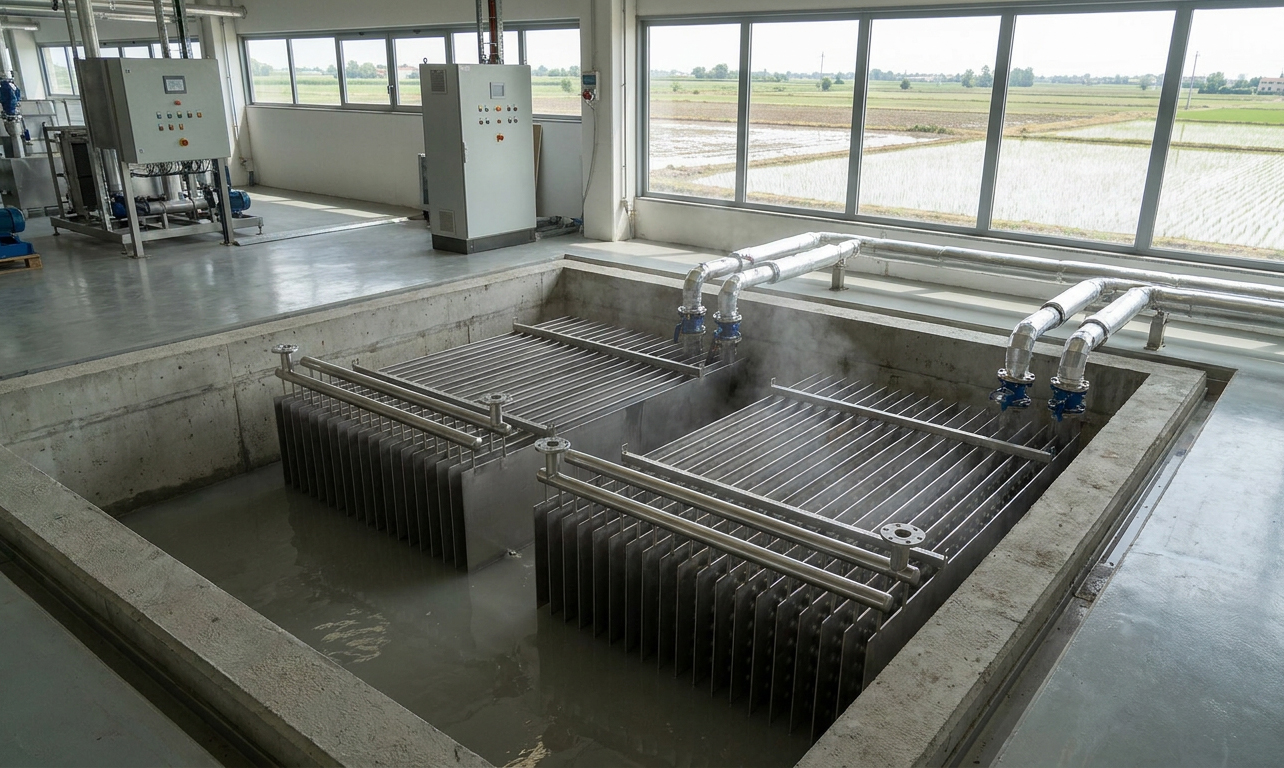
Tempco has implemented an interesting new energy-saving application using custom immersion plate heat exchangers for a client in the parboiled rice production sector. Specifically, for this project, Tempco manufactured and supplied two arrays of custom immersion heat exchangers—each consisting of 20 plates measuring 2500 x 500 mm, made of AISI 316L stainless steel with a 100 mm plate spacing. This custom application is of significant interest to energy managers and technical specialists across various industries, as it is ideally suited for other food and beverage production processes, as well as the chemical and pharmaceutical sectors.

In this specific case, the immersion plate heat exchanger arrays have been installed in the equalization tank, which receives the wastewater generated by the parboiling process—consisting primarily of water used to soak the paddy rice. The purpose of the custom immersion plate heat exchanger is to recover heat from the wastewater, yielding a dual benefit: first, the recovered heat preheats well water circulating within the plates to the highest possible temperature, resulting in significant energy savings by reducing steam consumption. Second, the heat transfer process cools the wastewater before it is sent to the purification plant, providing a substantial advantage for the biological treatment processes taking place there.

Image showing arrays of custom immersion plate heat exchangers in an equalization tank, designed for energy saving through heat recovery from wastewater generated during rice production.

The system was implemented as custom and in retrofit, utilizing existing structures within the client’s equalization tank. Specifically, the existing agitators were leveraged to maintain a fluid velocity of ≥0.1 m/s, generating turbulence that enhances heat transfer efficiency. Furthermore, the immersion heat exchanger arrays were installed by anchoring them to decommissioned aeration pipes (2.0 x 2.6 m).

Overall, the system will enable significant energy savings for the client, recovering approximately 174 kW of heat (150,000 kcal/h) and saving 1,500–1,700 tonnes of steam per year. Material selection for the heat exchanger plates was also critical; AISI 316L stainless steel was chosen to ensure corrosion resistance (handling wastewater with a pH of 3.7–3.9 with no critical chloride levels). Fouling caused by starches in the wastewater was accounted for using a conservative fouling factor (4E-4 m²K/W). Finally, given the intermittent nature of the wastewater flow—process wastewater is discharged every two hours, though a minimum volume is always maintained in the tank—performance was calculated at 70% of the theoretical maximum to determine the system’s ROI.

One fluid, many temperatures: how to regulate the temperature of a glass-lined reactor

Single-fluid thermoregulation is widely used in the pharmaceutical industry; Tempco recently supplied a TCU (Temperature Control Unit) to regulate the temperature of a glass-lined pharmaceutical reactor with a capacity of approximately 8,000 liters.

A natural question arises: why not feed utility fluids (glycol, water, steam) directly into the reactor jacket? While this might seem like the simplest approach, for glass-lined reactors, it would be a perfect recipe for disaster. Glass linings are highly sensitive to sudden temperature fluctuations; injecting steam at 8 bar immediately after glycol at -15°C risks causing catastrophic cracking.

The solution lies in the adoption of the mono-fluid temperature control concept across an extended range: a single heat-transfer fluid circulates continuously within the jacket’s closed loop, while three utility fluids (glycol at -15° C, industrial water at 25° C, and steam at 8 bar) condition its temperature outside the reactor itself.

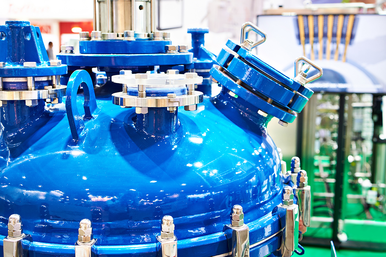
Image illustrating the single-fluid temperature control of a glass-lined pharmaceutical reactor, where a single fluid circulates within the jacket; the fluid's temperature is regulated externally to the reactor by three utility fluids—glycol, water, and steam—to prevent thermal shock and cracking of the glass lining.

The resulting advantage is clear: the intermediate fluid acts as a thermal buffer, ensuring excellent temperature uniformity across the vessel wall, thermoregulation precision within a tenth of a degree, and the elimination of thermal shock to the glass lining.

Five key data for heat exchangers sizing

Tempco has created a clear, concise tutorial to simplify the selection of data needed to size heat exchangers. When performing thermal calculations for heat exchangers, it is not necessary to provide every data point listed in the document for completeness – only a specific subset is required.

In fact, as indicated in the documentation, just five of the listed data are necessary and sufficient: the ‘must-have’ data – essential for initiating the sizing process- are those required for the thermal calculation:

  • Primary fluid inlet and outlet temperatures
  • Primary fluid flow rate
  • Secondary fluid inlet and outlet temperatures
  • Secondary fluid flow rate
  • Fluid pressure (crucial in the case of gases)

Capacity is another important factor for the thermal sizing of the exchanger; however, if the other five data are available, capacity can be calculated from them.

Image illustrating the essential and useful data for sizing heat exchangers.

The other data listed under the heading “DATA FOR HEAT EXCHANGERS DESIGN AND CONSTRUCTION” are useful for a more precise and comprehensive design but are not essential for an initial thermal calculation:

  • Fluid types
  • Max. operating temperature
  • Max. operating pressure
  • Oversizing % (margin)
  • Allowable pressure drops (primary and secondary)
  • Fluid viscosity
  • Fluid specific weight
  • Heat transfer coefficient
  • Fouling factor

In summary, to begin the sizing process, it is essential to provide at least five of the listed thermal parameters – including pressure if a gas is involved. The remaining data help refine the unit’s design specifications but are not required at the initial stage. It is important to note that for special fluids, you must contact Tempco directly, as specified in the document.

FIVE FINGERS RULE


Image illustrating the Tempco guide for selecting the data needed to size heat exchangers. Image illustrating the Tempco guide for selecting the data needed to size heat exchangers. Image illustrating the Tempco guide for selecting the data needed to size heat exchangers. Image illustrating the Tempco guide for selecting the data needed to size heat exchangers.

Custom dry coolers: stainless steel, ASME, and bespoke solutions for critical processes

When speaking about dry coolers, attention often shifts immediately to electrical components and ventilation systems. Yet, in many cases, it is the mechanical design that truly makes the difference.

There are applications involving aggressive cooling fluids or corrosive environments where standard copper tubing simply isn’t enough. Stainless steel coils are required to ensure durability and reliability, even under harsh conditions. In other instances, requirements are dictated by construction codes – such as ASME compliance – which are essential for systems destined for regulated sectors or markets where a certain certification is a mandatory requirement.

Image showing a series of dry coolers—industrial cooling systems where specialized mechanical designs often set them apart, making each unit unique in line with Tempco’s philosophy of tailor-made manufacturing.

These are concrete examples of how dry coolers can be transformed into unique units, engineered to meet highly specific needs. This is precisely where Tempco’s philosophy comes into play: offering solutions that go beyond mere cooling to support the client, addressing specific requirements through a ‘tailor made’ approach.

A dry cooler, therefore, is never just a dry cooler. It can become a critical component for reliability, safety, and process performance when designed using materials and standards suited to its actual operating environment.

Environment and chillers, phase-out of F-gases in new European regulation

European F-Gas legislation, governed by EU Regulation 2024/573, establishes rules for the use, containment, and phase-out of fluorinated greenhouse gases – substances responsible for global warming and having a high environmental impact if released.

F-gases are refrigerant gases essential for the operation of various types of equipment, such as air conditioners, heat pumps, gas-based fire suppression systems, chillers, and refrigeration plants.

Specifically regarding chillers, the new regulation imposes very strict limits on new installations starting January 1, 2027. These limits are based on Global Warming Potential (GWP) and establish the phasing out of certain types of F-gases in favor of low-environmental-impact gases or natural refrigerants.

Hence, the limits on refrigerant gas employ for newly manufactured chillers vary according to capacity:

  • Up to 12 kW capacity: From January 1, 2027, there is an absolute ban on using fluorinated gases with a GWP of 150 or higher (subject to specific exemptions where necessary to meet safety requirements).
  • Above 12 kW capacity: From January 1, 2027, the use of fluorinated refrigerants is permitted only if they have a GWP below 750.
  • From January 1, 2032: The regulation becomes even stricter, imposing a total ban on the use of any fluorinated gas.


Image showing the Tempco table regarding the new F-gas European regulation for the phase-out of refrigerant gases employed in chillers.


IP55-certified temperature control units for food & beverage

The food & beverage industry presents numerous thermoregulation and temperature control tasks for the various food production and processing of materials. The need for careful temperature regulation in the various processing steps must also meet important and stringent hygienic requirements to ensure product quality, food safety, and saveguard consumer’s health.

Temperature control units for use in food and beverage production lines must therefore meet stringent requirements in terms of materials and design, ensuring hygienic design of equipments. Thanks to an audit conducted by a notified body for the certification of the internal components of our TREG temperature control units, Tempco is therefore now able to provide IP55-certified temperature control units. The IP55 certification of a component specifically indicates the level of protection a device provides against the ingress of dust and liquids.

Illustrative image of Tempco TCU IP55-certified temperature control units for temperature control in the food and beverage industry.

This is further important addition to Tempco’s range of temperature control solutions for the food and beverage industry, where it already boasts a wide range of important and interesting applications, from chocolate processing to pasta, candies and sweets, milk, wine, and beer, to name just a few. The ability to offer internal components for our TCU specifically designed with IP55 protection, to meet the needs of the food and beverage market which requires the ability to wash down equipment with water jets, therefore opens up a wide variety of new application opportunities for Tempco, to even better meet the temperature control needs of the food industry.